
The global cryogenic valve market represents a critical segment of the industrial fluid control industry, driven by the escalating demand for Liquefied Natural Gas (LNG), industrial gases, and emerging hydrogen energy infrastructure. Valued at approximately USD 4.82 billion in 2025, the market is projected to expand to USD 8.91 billion by 2034, representing a compound annual growth rate (CAGR) of 6.80%. This growth is fundamentally linked to the unique physical challenges posed by ultra-low temperature environments, typically defined as ranging from -50°C to absolute zero. In these conditions, standard industrial valves are rendered ineffective due to material embrittlement, seal failure, and the catastrophic risks associated with fluid phase changes. Engineering a valve capable of maintaining bubble-tight shutoff at -196°C requires a sophisticated understanding of metallurgy, thermodynamics, and mechanical design, centered primarily on the extended bonnet and cold box integration strategies.
1. The Physics of Deep Cold: Material Integrity and Low-Temperature Embrittlement
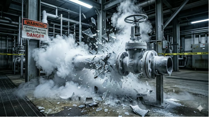
The most immediate challenge in cryogenic engineering is the survival of the valve structure itself. Conventional carbon steels, such as the ubiquitous ASTM A216 Grade WCB, are subject to the “Ductile-to-Brittle Transition” (DBT). As temperature decreases, the crystal lattice structure of ferritic steels—a body-centered cubic (BCC) arrangement—undergoes a fundamental shift that causes impact toughness to drop precipitously.
1.1 Metallurgical Transitions and Crystal Lattice Dynamics
At temperatures below -29°C, carbon steel effectively loses its ability to absorb energy through plastic deformation. In a cryogenic pipeline carrying liquid nitrogen (LN2) at -196°C, any mechanical shock or thermal contraction stress could lead to the instantaneous fracture of the valve body, a phenomenon colloquially known as “shattering like glass”.
| Material Grade | Crystal Structure | Min Service Temp | Thermal Conductivity (-196°C) | Charpy Impact at -196°C |
| ASTM A216 WCB | BCC | -29°C | ~15 W/m·K (Brittle) | < 5 J |
| ASTM A352 LCB | BCC | -46°C | ~16 W/m·K | 20-27 J |
| ASTM A351 CF8M (316) | FCC | -196°C | 7.2-8.6 W/m·K | > 100 J |
| Inconel 718 | FCC | -253°C | 6.5 W/m·K | > 150 J |
To counter this, engineers specify austenitic stainless steels (300 series), which possess a face-centered cubic (FCC) crystal structure. Unlike BCC metals, FCC metals do not exhibit a defined brittle transition point; instead, they maintain or even increase their strength and toughness as temperatures drop toward absolute zero.
Note: Data synthesized from multiple standards including ASME B16.34 and material property databases.
1.2 Thermal Conductivity and Heat Ingress Management
Beyond structural integrity, the thermal conductivity of the selected alloy plays a pivotal role in system efficiency. High thermal conductivity in valve components leads to “heat ingress,” where ambient heat is conducted into the super-cooled process fluid, causing unwanted vaporization or “boil-off gas” (BOG). Austenitic stainless steels like 316L are preferred not only for their toughness but also for their relatively low thermal conductivity compared to carbon steel, which facilitates better thermal isolation.
2. Engineering the Extended Bonnet: The Vapor Barrier Mechanism
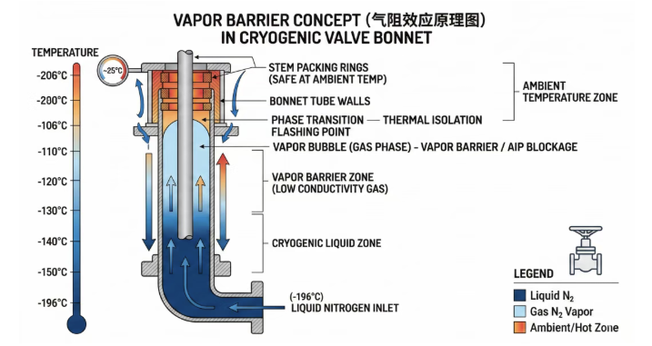
The most distinctive feature of a cryogenic control valve is its “long neck” or extended bonnet. This component is not merely a spacer; it is a functional thermodynamic device designed to protect the valve’s sealing integrity and operational reliability.
2.1 The Physics of the Gas Column (Vapor Barrier)
The primary failure point in cryogenic valves is the stem packing. Standard packing materials, such as PTFE (Teflon) or flexible graphite, require a degree of elasticity to maintain a seal against the valve stem. At -196°C, these materials become rigid, brittle, and lose their ability to “hug” the stem, resulting in catastrophic external leakage. Furthermore, if the stem is allowed to reach sub-zero temperatures at the packing interface, moisture from the ambient air will condense and freeze, forming ice crystals that act as abrasive particles, shredding the packing during valve actuation.
The extended bonnet solves this by creating a “vapor barrier” or insulating gas column. As cryogenic liquid enters the valve, a portion of it rises into the vertical extension of the bonnet. Due to heat transfer from the ambient environment through the upper portion of the metal extension, this liquid vaporizes. Because gas is a poor conductor of heat compared to liquid, this trapped gas column acts as a thermal buffer, keeping the packing area significantly warmer than the process fluid.
2.2 Mathematical Modeling of Heat Transfer
The design of the bonnet length (L) is governed by Fourier’s Law of Heat Conduction, aiming to ensure the packing temperature (Tp) remains within the safe operating range of the sealing material (typically above 0°C to prevent icing).

Where:
- Q is the rate of heat ingress.
- k is the thermal conductivity of the bonnet material.
- A is the cross-sectional area of the extension wall.
- L is the length of the extension.
By increasing the length and minimizing the wall thickness
(consistent with pressure rating requirements), engineers can effectively isolate the stuffing box from the cryogenic source.
3. Installation Orthodoxy and Orientation Constraints
The effectiveness of the vapor barrier mechanism is entirely dependent on gravity and fluid density differentials. This necessitates strict adherence to installation orientation.
3.1 The Vertical Rule
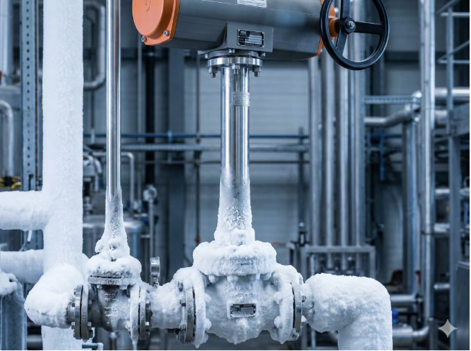
Cryogenic valves with extended bonnets must be installed with the stem in a vertical or near-vertical position. Most standards, including BS 6364 and MSS SP-134, recommend a deviation of no more than 15 to 45 degrees from the vertical axis.
If a cryogenic valve is installed horizontally, the dense cryogenic liquid will flow into the extension, displacing the gas column and coming into direct contact with the packing. This “flooding” of the bonnet leads to immediate freezing of the seals and operational failure. Consequently, the “vertical-up” orientation is an absolute mandate in LNG and air separation unit (ASU) piping designs.
4. Cold Box Integration and Drip Plate Design
In large-scale cryogenic processing facilities, valves are often grouped within a “cold box”—a massive, steel-encased enclosure filled with insulating materials like perlite (expanded volcanic glass) or utilizing a vacuum to minimize thermal transfer for the entire system.
4.1 Cold Box Extension Requirements
Valves designed for cold box service require significantly longer bonnet extensions than standard cryogenic valves. This is because the extension must pass through the thick layer of perlite insulation and the outer steel casing of the cold box, ensuring that the packing gland and actuator are accessible from the outside.
| Valve Size (NPS) | Non-Cold Box Extension (mm) | Cold Box Extension (mm) |
| NPS 2 / DN 50 | 400 | 500 |
| NPS 4 / DN 100 | 550 | 650 |
| NPS 8 / DN 200 | 650 | 750 |
| NPS 12 / DN 300 | 750 | 850 |
Data derived from industry standard MSS SP-134 Table 1A/1B references.
4.2 The Role of the Drip Plate
The “Drip Plate” (or deflector plate) is a critical auxiliary component welded to the bonnet extension just above the insulation boundary. Its primary function is to divert atmospheric condensation away from the valve. In cryogenic service, the exposed upper metal of the bonnet is extremely cold, causing water vapor from the air to condense into liquid or frost. Without a drip plate, this moisture would run down the stem into the cold box, where it would freeze into a solid block of ice, destroying the insulating properties of the perlite and potentially jamming the valve stem.
5. Maintenance Architectures: Top-Entry vs. Side-Entry
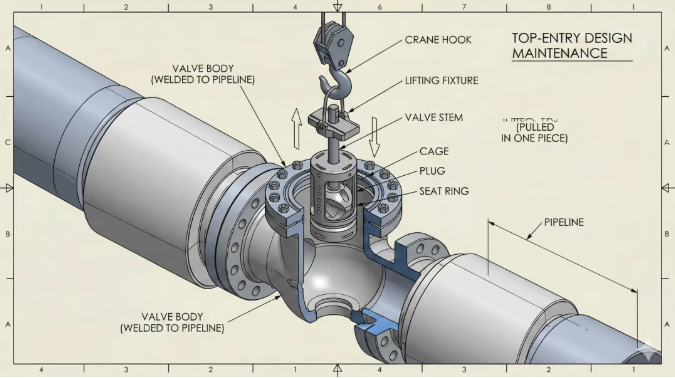
In cryogenic systems, particularly those involving cold boxes or vacuum-jacketed piping, the method of valve maintenance is a primary design consideration. Because flange joints are prone to leakage under extreme thermal cycling (due to bolt relaxation and gasket contraction), many cryogenic valves are permanently welded into the pipeline.
5.1 The Strategic Advantage of Top-Entry Designs
For welded-in valves, a “top-entry” design is mandatory. A top-entry ball or globe valve allows all internal components—including the ball, seats, and stem—to be removed through the top of the bonnet without cutting the valve out of the line. This is especially vital in cold boxes, where accessing the valve body would require draining the perlite insulation and breaching the steel shell.
Top-entry valves are structurally superior for high-pressure cryogenic service as they are often cast from a single piece of steel, reducing potential leak paths compared to split-body (side-entry) designs. While side-entry valves are more cost-effective for general industrial use, their requirement for pipeline disassembly makes them unsuitable for critical-path cryogenic infrastructure.
6. Cavity Pressure Relief and Operational Safety
Cryogenic fluids exhibit extreme expansion ratios. For example, Liquid Natural Gas (LNG) expands approximately 600 times in volume when it vaporizes into gas. This physical property creates a significant hazard for valves with enclosed cavities, such as ball and gate valves.
6.1 The Risk of Thermal Over-Pressurization
If liquid is trapped in the body cavity of a closed valve, even a minor ingress of heat will cause the liquid to vaporize. A temperature rise of only 1°F can increase the pressure in a trapped cavity by up to 100 psi. This rapid pressure buildup can cause the seats to deform, the stem to bind, or in extreme cases, the valve body to rupture explosively.
6.2 Relief Mechanisms: Vents and Self-Relieving Seats
To mitigate this, cryogenic valves must incorporate pressure relief mechanisms:
- Vented Ball/Wedge: A small relief hole is drilled into the upstream side of the ball or wedge. This ensures that the cavity is always balanced with the upstream pipeline pressure, preventing entrapment. This makes the valve unidirectional.
- Self-Relieving Seats: Specialized seat designs allow the cavity pressure to “push back” the seat against its spring, bleeding excess pressure back into the pipeline.
- Automatic Cavity Relief (APR): In larger gate valves, an external relief valve may be installed to connect the cavity to the upstream side.
7. The Regulatory Landscape: MSS SP-134, BS 6364, and ISO 21011
The design and testing of cryogenic valves are governed by several key international standards, each with its own focus and regional dominance.
7.1 MSS SP-134 (Manufacturers Standardization Society)
MSS SP-134 is the primary North American standard for cryogenic valves with extended bonnets. It provides rigorous guidelines for material selection (referencing ASME B16.34) and defines specific dimensions for extension lengths. It is unique in providing standardized tables (Table 1A and 1B) that dictate minimum extension lengths based on nominal pipe size and service type (cold box vs. non-cold box).
7.2 BS 6364 (British Standard)
BS 6364 is widely used in Europe and for many international LNG projects. It is particularly noted for its detailed leakage rate criteria, measured in cc/min per inch of nominal bore. It also provides specific operational mandates, such as the requirement for valves in liquid service to operate at an angle of 45° or higher from the horizontal.
7.3 ISO 21011 (International Organization for Standardization)
ISO 21011 provides a modern, global framework for cryogenic valves, emphasizing the use of materials that remain ductile at minimum temperatures (ISO 21028-1/2). It explicitly forbids the presence of cavities that could trap liquid and requires that all non-metallic seals resist aging and environmental degradation.
| Feature | MSS SP-134 | BS 6364 | ISO 21011 |
| Primary Region | North America | Europe / International | Global |
| Extension Length | Detailed dimensional tables | Performance-based | General guidelines |
| Stem Orientation | 15° to 90° | 45° (Liquid) / 15° (Cold Box) | Sufficient to protect packing |
| Testing Focus | Design & Dimensions | Leakage Rates (cc/min) | Safety & Material Compatibility |
Comparison based on analysis of contemporary standards.
8. Quality Assurance: Cryogenic Testing and NDE
The critical nature of cryogenic service necessitates extensive testing, both at the prototype stage and for production units.
8.1 Low-Temperature Acceptance Tests
The “Cryogenic Test” involves submerging the valve body in a bath of liquid nitrogen (-196°C). Once thermal equilibrium is reached, the valve is operated through its full cycle to check for stem binding, torque increases, and seal integrity. Because standard air or water testing is impossible at these temperatures, high-purity helium is used as the test medium. Helium mass spectrometry is utilized to detect micro-leaks that would be invisible to traditional bubble-testing methods.
8.2 Non-Destructive Examination (NDE)
For high-integrity cryogenic service, standard visual inspection is insufficient.
- Radiographic Testing (RT): Mandated for casting integrity to ensure no subsurface voids exist that could act as stress concentrators during thermal shock.
- Impact Testing: Material heats are subjected to Charpy V-notch tests at the design minimum temperature to verify impact energy values.
- Fugitive Emission Testing: Required for environmental compliance, especially in methane (LNG) service, ensuring the stem packing meets ISO 15848-1 or API 622/624 standards.
9. B2B Procurement Strategy and RFQ Optimization
Procuring cryogenic valves is a complex process that requires deep technical alignment between the engineer, the buyer, and the manufacturer. A poorly drafted Request for Quotation (RFQ) leads to multiple clarification rounds and significant project delays.
9.1 The Engineering-Driven RFQ Checklist
To ensure accurate pricing and technical compliance, procurement teams must provide:
- Absolute Minimum Design Temperature: Not just the operating temperature, but the upset or blowdown temperature.
- Media and Cleanliness: Liquid oxygen (LOX) requires strict hydrocarbon-free cleaning and specialized lubricants; hydrogen requires materials resistant to hydrogen embrittlement.
- Actuation Cycles: High-frequency cycling in control valves demands more robust seat designs (e.g., Stellite cladding) compared to isolation valves.
- Required Standards: Explicitly state if compliance is required for MSS SP-134, BS 6364, or specific end-user specifications (e.g., Shell 77/200).
9.2 SEO and Digital Sourcing Trends in the Valve Industry
From a market perspective, B2B search behavior for cryogenic equipment has become highly technical. Buyers are no longer searching for general terms like “LNG valves”; they are searching for long-tail, engineering-specific queries such as “top entry cryogenic ball valve MSS SP-134 compliant” or “low-leakage globe valve for liquid nitrogen service”. Manufacturers who provide deep technical content—including GA drawings, spec sheets, and third-party test reports—are establishing higher trust (EEAT) and capturing more high-value engineering contracts in the midstream and downstream sectors.
10. Future Horizons: Hydrogen and Carbon Capture
As the global energy transition accelerates, cryogenic valve technology is being pushed to new limits by the liquid hydrogen (LH2) and carbon capture sectors.
10.1 The Hydrogen Challenge (-253°C)
Liquid hydrogen service is significantly more demanding than LNG. At 20K (-253°C), almost all gases except helium solidify, and even 316L stainless steel can be susceptible to hydrogen-assisted cracking if not properly specified. The industry is seeing a shift toward “vacuum-jacketed” (VJ) valves, where the valve body is enclosed in a second shell with a high-vacuum annulus, providing the ultimate level of thermal insulation for the hydrogen economy.
10.2 Sustainability and Digital Twins
Future cryogenic infrastructure will increasingly utilize “Smart Valves” equipped with digital diagnostics. These systems can monitor thermal gradients across the extended bonnet in real-time, predicting seal failure or icing issues before they lead to plant shutdowns. Furthermore, the push for “Zero Fugitive Emissions” is driving the adoption of bellows-sealed valves and live-loaded packing glands across all ultra-low temperature applications.
11. Conclusion: Engineering for Extreme Reliability
The engineering of cryogenic valves is a testament to the mastery of material science and thermodynamics in the pursuit of industrial safety. The transition from standard carbon steel to austenitic alloys, the implementation of the extended bonnet’s vapor barrier, and the rigorous adherence to orientation and maintenance protocols are not optional design choices—they are the fundamental pillars of cryogenic infrastructure. As the demand for LNG and liquid hydrogen grows, the reliability of these valves will remain the linchpin of the global energy transition, ensuring that the world’s coldest fluids are controlled with precision and absolute integrity.