
When reviewing a control valve data sheet, you will often come across an impressive specification:
Rangeability: 50:1, or even 100:1.
Many engineers see this figure and feel reassured: “My maximum flow rate is 100, and my minimum flow rate is 2. The required ratio is only 50:1, so this valve should easily handle the job.”
But then reality strikes once the valve is installed:
At low flow rates, the valve oscillates wildly. Alternatively, at high flow rates, the valve may be only 80% open, yet the flow rate refuses to increase any further.
Why does the catalog data seem to have misled you?
Today, we will uncover the harsh reality behind the difference between inherent rangeability and installed rangeability.
1. The Ideal World: Inherent Rangeability
The rangeability stated in a manufacturer’s catalog, or measured in a laboratory, is known as inherent rangeability.
Its definition is straightforward: the ratio of the maximum controllable flow rate to the minimum controllable flow rate under a constant pressure differential across the valve.
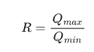
Pay attention to the key phrase: constant pressure differential.
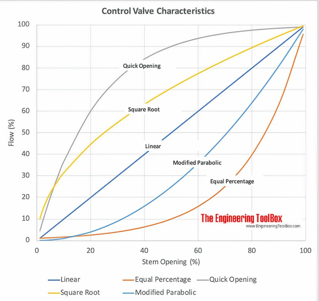
Think of it as testing a car’s performance on a smooth, straight, wind-free professional racetrack. The result is its “top speed” under ideal conditions.
In a laboratory, the pump has sufficient capacity, and there are no complicated piping-system pressure losses to consider. Regardless of how far the valve is opened, the pressure differential between the upstream and downstream sides is maintained at, for example, 1 bar.
Under these ideal conditions, modern control valves can indeed achieve an inherent rangeability of 50:1 or even higher.
2. The Real World: Installed Rangeability
In reality, your valve is installed in a process system full of elbows, heat exchangers, orifice plates, and long pipe runs.
This is where installed rangeability comes into play. In an actual system, the pressure differential across the valve changes as the valve opening changes.
Why Does the Pressure Differential Change?
Consider a fundamental relationship derived from Bernoulli’s principle:
Total system pressure differential = Pressure drop across the valve + Pressure losses in the piping system
When the valve is nearly closed: The flow rate is low, so frictional losses in the piping are relatively small. A larger proportion of the available pump head is absorbed by the valve. The pressure differential across the valve is therefore relatively high.
When the valve opens wider: The flow rate increases, and pressure losses across the pipes, elbows, heat exchangers, and other components rise. For many turbulent-flow systems, these losses are approximately proportional to the square of the flow rate. As a result, less of the available pressure differential may remain across the valve.
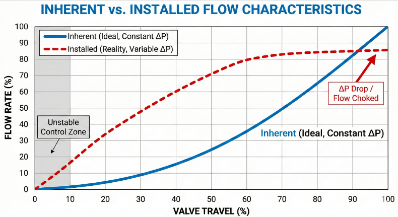
The Consequences of a Distorted Flow Characteristic
When the pressure differential across the valve decreases significantly at high flow rates, the valve’s capacity to increase flow becomes limited.
What the catalog says: At 100% opening, the valve can pass 100 tonnes of water per hour.
What may happen in practice: Because the pressure differential across the valve becomes too low at high flow rates, the flow may begin to level off when the valve is only 80% open. The remaining 20% of the valve travel provides little additional flow.
At small openings, the opposite problem may occur. A relatively high pressure differential can make even a small change in valve opening produce a substantial change in flow, potentially resulting in unstable control.
The result: The usable installed rangeability may be reduced significantly, sometimes to 10:1 or even less, depending on the system design and operating conditions.
3. Why Are Small Valve Openings a “Danger Zone”?
Another common misconception is: “If the valve has a rangeability of 50:1, surely I can control the flow at a 2% opening.”
Be careful. The minimum controllable flow is limited by more than just the flow coefficient, Cv. Physical and mechanical factors also play a role.
Clearance Flow and Erosion
At extremely small openings, such as below 5%, the fluid may pass through a very narrow clearance between the valve plug and seat at high velocity. Under certain conditions, this high-velocity jet can erode or damage the sealing surfaces, eventually causing excessive internal leakage.
Friction and Deadband
As discussed in the next article, No.009, control valves are subject to friction. At very small openings, friction can represent a significant proportion of the actuator’s effective movement. This may cause the valve to stick and then suddenly jump.
For example, you may command the valve to open by 1%, but it does not move. When you increase the control signal further, it suddenly jumps to 3%. This nonlinear behavior can seriously impair PID control performance.
Engineering Guideline
As a preliminary rule of thumb, a minimum operating opening of around 10% is sometimes recommended for control valves, while high-performance designs may be capable of operating at openings as low as 5%.
A maximum operating opening of around 90% may also be used as a design guideline to preserve some control margin.
However, these are not universal limits. The appropriate operating range depends on the valve design, actuator performance, process conditions, and the manufacturer’s recommendations.
4. Who Steals Your Rangeability? — Valve Authority
If rangeability is reduced in real installations, what determines the extent of that reduction?
The answer is valve authority, commonly represented by the symbol Pr.
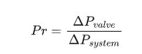
Simply put, valve authority is the proportion of the total relevant system pressure drop that occurs across the control valve under a specified operating condition.
When Pr = 1: The entire relevant pressure drop occurs across the valve, representing an idealized condition with negligible pressure loss elsewhere in the system. The installed flow characteristic can approach the inherent characteristic, and installed rangeability can approach inherent rangeability.
When Pr =0.1: A larger proportion of the pressure drop is consumed by the rest of the system. The valve has less influence over the overall flow, and its installed flow characteristic may become significantly distorted.
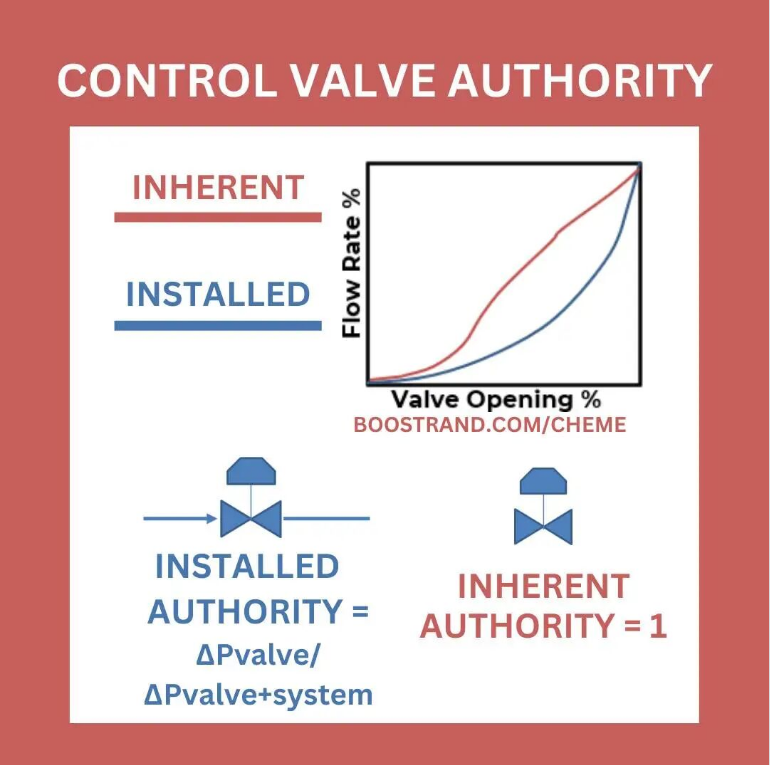
In engineering design, we often want to reduce the pressure drop across the valve to save energy, rather than wasting excessive pump power across the valve.
However, energy efficiency and control performance can be competing objectives. If valve authority is too low—for example, below 0.3—the valve may become much more difficult to control effectively.
The appropriate target for valve authority depends on the application and the overall system design.
5. What Can You Do? Practical Engineering Tips
When a process requires an exceptionally wide flow-control range—for example, during startup and normal operation of a large chemical plant, or when operating loads differ substantially between summer and winter—do not blindly trust a manufacturer’s “100:1” catalog figure.
Solution 1: Calculate Valve Authority
During valve selection, do not provide only the maximum-flow operating case. You must also provide the pressure differential available across the valve at minimum flow.
Ask the manufacturer or sizing engineer to evaluate the installed flow characteristic using appropriate sizing software and realistic system operating conditions.
Solution 2: Use Split-Range Control
Split-range control is a well-established approach for handling a wide required flow range.
One possible arrangement uses two valves in parallel:
A large valve handles the main flow range.
A small valve provides precise control at low flow rates.
For example, the control strategy could be configured as follows:
0%–30% control signal: The small valve operates while the large valve remains closed.
30%–100% control signal: The small valve remains fully open, and the large valve begins to open.
When properly sized and configured, this arrangement can substantially increase the overall controllable flow range and may achieve an effective rangeability of 100:1 or higher.
The actual result depends on valve sizing, overlap between the operating ranges, actuator resolution, and the control strategy.
Solution 3: Select a Different Valve Design
V-port ball valves (V-ball valves) and eccentric rotary control valves, such as Camflex-style designs, may offer favorable inherent rangeability and control characteristics for certain applications.
Depending on the design, they may also be suitable for demanding services involving high pressure drops or erosion risks. However, resistance to cavitation and erosion must be assessed for the specific service conditions; it should not be assumed from valve type alone.
🚀 Coming Next
If your valve constantly oscillates around the setpoint or remains stuck before suddenly moving, the problem may not be the PID tuning. The underlying cause may be mechanical or physical.
In the next article, “The Ghost in the Control Loop: Understanding the Differences Between Deadband, Hysteresis, and Stiction,” we will explore the dynamic problems that can undermine control valve performance.