
Have you ever encountered either of these situations?
The flow trend on the DCS remains a perfectly flat line, even though it responds when the setpoint changes.
Or the flow trend oscillates continuously like a sine wave. No matter how gently you tune the PID parameters, the oscillation just will not stop.
When this happens, stop tweaking the PID parameters for a moment. The problem may lie in the valve itself.
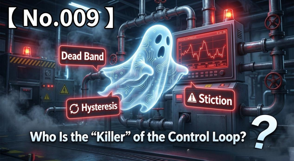
In a control valve’s “health report,” there are three symptoms that sound similar but are fundamentally different: Deadband, Hysteresis, and Stiction.
Today, we will track down these three ghosts and find out which one may be sabotaging your control accuracy.
1. Deadband: The Slack in the Steering Wheel
Definition:
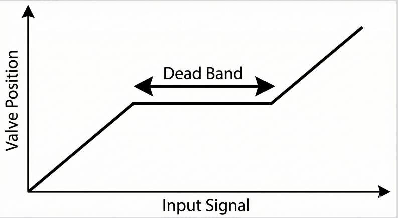
Deadband is the range over which the input signal changes direction, but the valve stem—the output—does not move.
A Simple Analogy:
Imagine driving an old, worn-out truck. You want to turn left, so you turn the steering wheel by 5 degrees, but the wheels do not move. You turn it by 10 degrees, and still nothing happens. Only when you turn it by 15 degrees do the wheels finally begin to turn.
That 15-degree range of “slack” is analogous to deadband.
Causes:
Deadband is often associated with mechanical clearance or backlash in connections and linkages, such as:
Clearance in the connection between the valve stem and actuator stem connector.
Gear backlash in rack-and-pinion actuators.
Loose linkages in a positioner’s feedback mechanism.
Consequences:
Within the deadband, commands from the controller may have no effect on valve movement. If the deadband is excessive—for example, 5%—the controller may attempt small corrections when the error is small, but the valve will not respond. As the error accumulates, the controller may issue a larger command, causing the valve to move abruptly and overshoot the target.
Key Symptom: The valve appears to “ignore” small changes when the direction of movement reverses.
2. Hysteresis: The Return Path Never Quite Matches
Definition:
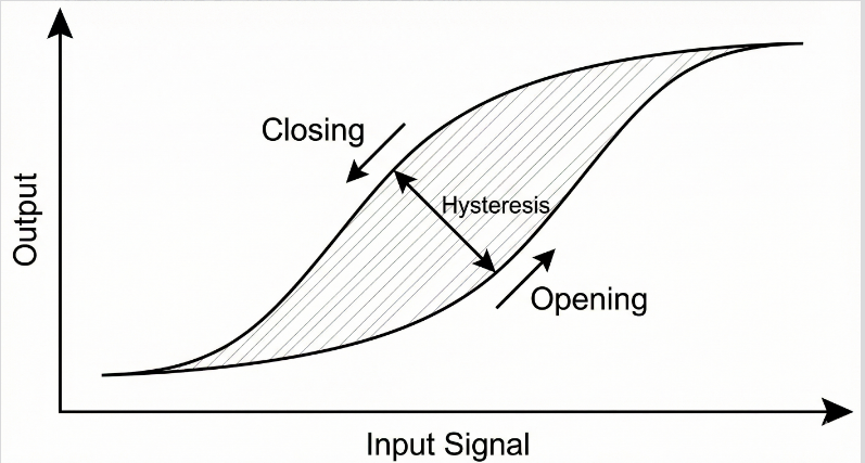
Hysteresis occurs when the actual valve position differs at the same input signal, depending on whether the signal is increasing from 0% to 100% or decreasing from 100% to 0%.
A Simple Analogy:
Imagine hiking up and down a mountain. On the way up, carrying a backpack, your heart rate is 150 beats per minute when you reach a particular landmark. On the way down, you pass the same landmark with a heart rate of only 90 beats per minute.
You are at the same location, but your physical state is different depending on the direction from which you arrived.
Causes:
Hysteresis can result from non-ideal elastic behavior, magnetic effects in components where relevant, and friction. Friction is often a significant contributor in control valve assemblies.
With the widespread use of modern digital positioners, hysteresis is not always reported as an isolated performance parameter. Manufacturers may specify combined performance figures that include effects such as deadband and hysteresis, depending on the applicable test method.
Consequences:
Suppose a 50% input signal produces a valve position of 51% while the signal is increasing. When the signal is reduced from 100% to 50%, the valve may instead settle at 49%.
The same input signal therefore produces different valve positions depending on the direction of travel, potentially reducing control accuracy.
Key Symptom: At the same input signal, the valve does not return to the same position when the direction of movement is reversed.
3. Stiction: The Most Dangerous “Control Loop Killer”
While the first two phenomena can reduce control accuracy, stiction can be a major cause of control loop instability.
The term stiction combines the ideas of static friction and friction during motion.
Definition:
When the valve is stationary, static friction may be high enough to prevent movement, effectively causing the valve to stick. As the actuator force builds and finally overcomes the static friction, the valve suddenly starts moving. Because the friction during motion may be lower than the breakaway friction, the resistance drops abruptly, and the valve may jump suddenly—a phenomenon known as stick-slip motion.
A Simple Analogy:
Imagine pushing a heavy box across the floor.
You push gently, but the box does not move.
You push harder, but it still stays put because static friction is high.
You finally give it a strong shove, and suddenly it slides much farther than expected.
You quickly reduce your effort, and the box slows or stops again.
This is the basic idea behind stick-slip motion.
Consequences:
Stiction can cause a control loop to develop a limit cycle, in which the process variable repeatedly oscillates instead of settling at the setpoint.
A typical sequence may look like this:
The DCS issues a small correction, but the valve remains stuck.
The process error increases, and the integral term (I) continues accumulating, driving the controller output further.
Eventually, the actuator force overcomes static friction, and the valve suddenly jumps—often moving farther than needed.
The DCS responds by correcting in the opposite direction, but the valve sticks again.
The cycle repeats, producing a recurring oscillation in the flow trend, sometimes resembling a square wave or sine wave.
Key Symptom: The valve either does not move at all or moves in sudden jumps, making it difficult to hold the process variable steadily at the setpoint.
4. How Can You Tell Them Apart? — Practical Field Diagnostics
How can you use DCS trends to determine whether the problem is poor controller tuning or valve stiction?
One useful diagnostic approach is a small-step test, also called a bump test in some contexts.
Place the control loop in manual mode (MAN), ensure the test can be performed safely, and apply a series of small step changes to the valve command—for example, increments of 0.5% or 1%.
Ideal Valve: A 1% command change produces approximately a 1% movement, with a smooth, orderly response. Actual behavior depends on the valve and actuator characteristics.
Valve with Deadband: A 1% command change produces no movement. A further 1% change may finally cause the valve to move.
Valve with Stiction:
Increase the command by 1%: no movement.
Increase it by another 1%: still no movement.
Increase it again: the valve suddenly jumps by 3–4%.
This is a typical example of stick-slip behavior.
Important: A small-step test should be conducted by qualified personnel under appropriate operating procedures. Valve command, position feedback, and process-variable trends should be compared where available. Deadband and stiction can coexist, so a single test may not conclusively distinguish them.
5. How to Fix the Problem
Now that we have identified the ghosts, how do we get rid of them?
1. Addressing Deadband
Check whether the valve stem connector and other mechanical connections are loose.
Inspect the positioner’s feedback linkage and associated connections.
If gear wear or excessive backlash is present, repair or replace the affected components. In some cases, actuator replacement may be necessary.
2. Addressing Stiction — The More Difficult Problem
A. Check for Excessive Packing Friction
Over-tightened valve packing is a common potential cause of high stem friction. Graphite packing, in particular, may generate significant friction if improperly installed or compressed too tightly.
Inspect the packing and follow the manufacturer’s maintenance procedure to determine whether adjustment is appropriate. Do not simply loosen the packing gland nuts without checking the valve design and safety requirements, as this may cause external leakage or create a hazardous condition.
B. Optimize the Positioner Settings
If the valve uses a smart positioner, such as the Fisher DVC6200 or Siemens SIPART PS2, review the device diagnostics and configuration.
Depending on the model and available functions, positioner tuning may help improve response or compensate for certain friction-related effects. However, increasing gain or making the pneumatic output more aggressive will not necessarily eliminate mechanical stiction and may introduce instability. Follow the manufacturer’s instructions and verify the results under actual operating conditions.
C. Consider a Larger Actuator Where Necessary
If the actuator does not provide sufficient thrust to overcome the forces acting on the valve under the required operating conditions, a larger actuator may be necessary.
The selection must account for process forces, packing friction, spring force, required seating force, and available supply pressure. Simply increasing actuator size will not necessarily solve stiction caused by damaged or poorly maintained components.
The concept of bench set is also relevant to actuator sizing and calibration; we will discuss it in the next article.
Summary
Deadband is “slack”: small command changes may produce no movement.
Hysteresis is “direction-dependent behavior”: the same input can produce different positions depending on the direction of travel.
Stiction is “stick-slip motion”: the valve sticks, then jumps, potentially causing recurring control loop oscillations.
If your PID loop remains unstable no matter how you tune it, stop focusing exclusively on the controller. Investigate the valve assembly, positioner, actuator, and packing to determine whether mechanical friction or other valve-related problems are contributing to the instability.