
Keywords: Cv Value, Kv Value, Flow Calculation, Valve Sizing, Choked Flow
📝 Introduction: Key Takeaways
On a control valve datasheet, one of the most prominent parameters is always the Cv value.
It is the “currency” of a valve’s flow capacity. If the valve is oversized, it may operate at very small openings for extended periods, potentially causing oscillation and reducing its service life. If it is undersized, even at full opening, it may fail to meet production requirements, becoming a bottleneck in the process.

Many engineers believe that calculating Cv is simple: “Can’t you just plug the numbers into a formula?”

That is true as far as the basics are concerned. However, in real-world engineering applications, pitfalls such as viscosity correction, choked flow, and piping geometry corrections are everywhere.
A small oversight can result in a calculated Cv that is significantly lower than the actual requirement.
In this article, we return to the mathematics to develop a thorough understanding of this essential valve parameter.
01. The Origins of the Definition: Imperial vs. Metric Units
Cv (Flow Coefficient) originated in the United States and has become a common language in the fluid control industry.
Definition: The number of US gallons per minute (US gpm) of water at 60°F (15.6°C) that flows through a valve with a pressure drop of 1 psi (6.89 kPa) across the valve.
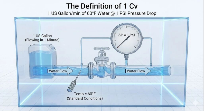
Kv is its European metric counterpart.
Definition: The number of cubic meters per hour (m³/h) of water that flows through a valve with a pressure drop of 1 bar, under the applicable reference conditions specified for the Kv definition.
🔢 Conversion Formulas to Remember
Cv = 1.156 × Kv
Kv = 0.865 × Cv
💡 Tip to Avoid Mistakes: When reviewing datasheets from international valve manufacturers, always check whether the flow coefficient is expressed as Cv or Kv. If you mistakenly treat a Kv value as a Cv value, you may underestimate the required flow capacity by approximately 13–15%.
02. The Assumptions Behind the Basic Formula
For incompressible fluids, such as liquids under non-flashing conditions, a simplified flow-sizing relationship can be expressed as:
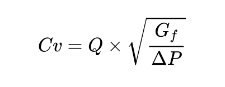
Where:
Cv: Valve flow coefficient
Q: Flow rate (US gpm)
Gf: Liquid specific gravity relative to water (water = 1.0)
ΔP: Pressure drop across the valve (psi)
This formula relies on an important assumption: the fluid behaves approximately as a Newtonian liquid, and no phase change occurs.
Once these assumptions are violated, the calculation must be corrected to account for the actual fluid behavior and operating conditions.
03. Pitfall No. 1: High-Viscosity Fluids
When handling heavy oil, polymers, syrup, or other highly viscous fluids, viscous forces significantly resist flow.
If the basic formula is applied without correction, the calculated Cv may substantially underestimate the actual flow capacity required.
Correction Method: Valve Reynolds Number (Rev)
The valve Reynolds number must be evaluated to determine whether viscosity correction is necessary.
When Rev > 10,000: Flow is generally turbulent, and viscosity correction may be unnecessary under the applicable sizing criteria.
When Rev < 10,000: Flow may be transitional or laminar, and a viscosity correction factor, FR, may be required.
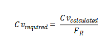
At extremely high viscosities, FR may be as low as 0.5 in some cases.
This means that the valve may require approximately twice the theoretical flow coefficient calculated without viscosity correction to achieve the same flow rate under the specified conditions.
The actual correction depends on the valve geometry, fluid properties, Reynolds number, and applicable sizing procedure.
04. Pitfall No. 2: Choked Flow and the FL Factor
This is one of the most important pitfalls in control valve sizing.
According to the basic formula, for a fixed Cv value, flow rate Q increases as the pressure drop ΔP increases.
Intuition tells us that a greater pressure drop produces a higher flow rate.
However, physics imposes a limit.
When the pressure at the vena contracta inside a valve falls below the liquid’s vapor pressure, vapor bubbles may form. Depending on downstream pressure and the fluid’s vapor pressure, these bubbles may collapse downstream or persist as vapor. These phenomena are associated with cavitation and flashing, respectively, as discussed in Article No. 001.
Under choked-flow conditions, the flow rate no longer increases proportionally with additional pressure drop.
If the actual pressure drop is then used indiscriminately in the basic sizing equation, the calculated Cv may be misleading and may underestimate the capacity required for the application.
✅ The Correct Approach
During valve sizing, the maximum allowable pressure drop must be evaluated. For liquid sizing, this is commonly associated with the choked-flow pressure-drop limit, often denoted as ΔPchoked or ΔPmax in a given calculation method.
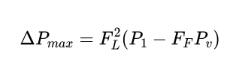
The FL factor is the liquid pressure recovery factor. It characterizes the pressure recovery behavior of a valve and depends on its design.
Illustrative values may include:
Cage-guided globe valves: FL around 0.9 in some designs.
Ball valves: FL around 0.6 in some designs.
These are examples only; actual values must be obtained from the manufacturer’s technical data for the specific valve and trim configuration.
If the actual pressure drop exceeds the applicable choked-flow limit, the sizing calculation must account for that limit rather than assuming that the full pressure drop will continue to increase the flow rate.
The appropriate calculation should follow the applicable control valve sizing standard and the manufacturer’s recommended procedure.
🚀 Summary
Cv calculation is not simply an exercise in algebra. It is a process of evaluating fluid behavior under actual operating conditions.
Keep these three checks in mind:
1. Confirm the units
Is the flow coefficient expressed as Cv or Kv?
2. Check the viscosity
Does the fluid require an FR viscosity correction?
3. Check for choked flow
Does the actual pressure drop exceed the applicable maximum pressure drop for the valve and fluid conditions?
Correctly evaluating these factors is essential for reliable valve sizing and control performance.