In previous articles, we have discussed either macroscopic flow characteristics, such as rangeability, or microscopic dynamic errors, such as deadband and stiction.
But one fundamental question remains unanswered: What actually makes a valve move?
When a pipeline carries fluid at a high pressure of 100 bar, or when a valve is so large that a person could crawl inside it, how much force is required to press the valve plug against the seat and achieve tight shutoff?
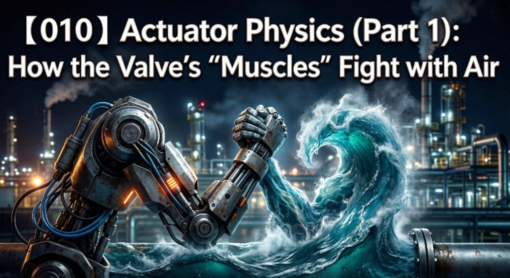
The force comes from the actuator. For the most common type of control valve actuator—the pneumatic actuator—the underlying principle comes down to one of the most fundamental equations in physics:
Force = Pressure × Area
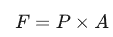
Today, we will use this equation to examine the two most widely used types of pneumatic actuators: diaphragm actuators and piston actuators, and explore how they balance forces.
1. The Gentle Giant: Pneumatic Diaphragm Actuator
The pneumatic diaphragm actuator is one of the most established and widely used actuator types in the process industries. Its core component is a circular diaphragm, typically made from reinforced elastomer.
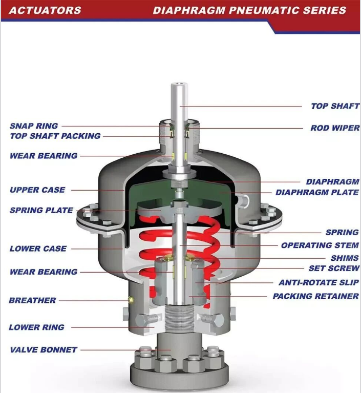
How It Works: Air Pressure Fighting Against a Spring
Imagine trying to inflate a balloon while someone presses against it to prevent it from expanding.
Driving force (Fₚ): Compressed air, supplied through the control system and positioner as applicable, enters the diaphragm chamber and acts over the diaphragm’s effective area to generate thrust.
Opposing force (Fₛ): A large spring is installed on the other side of the diaphragm. The pneumatic force must overcome the spring’s preload and the additional spring force generated as the spring is compressed or extended before the actuator can move the valve stem.
Force-Balance Analysis
When the valve is stable at a particular position, the actuator is approximately in force balance. For simplicity, we will initially ignore friction and fluid-induced forces to focus on the main principles.
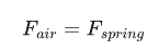
The basic relationship is:
Pneumatic force = Air pressure × Effective diaphragm area

At equilibrium, this force balances the spring force and any other forces acting on the actuator.
Let’s break down the key variables:
P (Air pressure): This is the input variable. The operating pressure of a conventional pneumatic diaphragm actuator is often within a relatively low range, commonly around 0.2–1.0 bar or 0.4–2.0 bar depending on the design and application. The maximum allowable pressure is determined by the actuator manufacturer’s specifications and must not be exceeded.
A (Effective area): This is the key to generating sufficient thrust at relatively low air pressure. The diaphragm needs a sufficiently large effective area. Just as a hydraulic jack can lift a car by applying pressure over a large area, increasing the effective area increases the force generated at a given pressure.
Fₛ (Spring force): The spring force depends on the spring preload, spring rate, and displacement. As the actuator moves and the spring is compressed further, the force required to move it generally increases.
Characteristics of Diaphragm Actuators
Advantages: Relatively simple construction, generally low friction, reliable spring-return action, and a fail-safe position in spring-return designs when the air supply is lost.
Disadvantages: Limited output force compared with many high-pressure piston actuators. Since operating pressure is relatively low, higher thrust may require a larger diaphragm housing. The available stroke is also limited in many conventional designs.
2. The Powerful Boxer: Pneumatic Piston Actuator
When the valve is large, the pressure differential is high, or extremely fast operation is required, a conventional diaphragm actuator may not provide sufficient force or stroke. In these cases, a piston actuator may be a better choice.
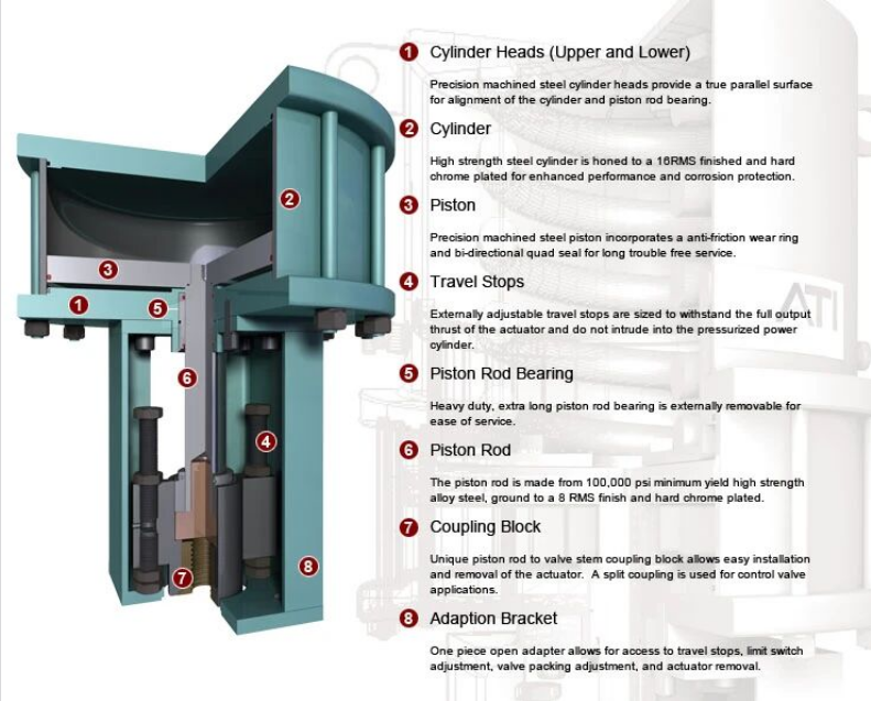
Its core component is a rigid piston that moves inside a cylinder.
How It Works: Push and Pull Like a Syringe
Imagine a large medical syringe. Compressed air enters one side of the cylinder and pushes the piston, producing linear movement.
Force-Balance Analysis
Pneumatic piston actuators are available in double-acting and single-acting spring-return configurations.
For this explanation, we will focus on a double-acting piston actuator, which uses compressed air to drive movement in both directions and does not rely on a return spring.
When the valve needs to move downward to close—for example, when air is supplied to the upper chamber—the key factors are:

P (top_air): This is one of the main advantages of piston actuators. Depending on the design and plant air supply, they may operate at pressures of 6–10 bar or higher. The actual allowable operating pressure must be verified against the actuator specifications.
A (Piston_top): Although the piston diameter may be smaller than the diameter of a diaphragm housing, the combination of a suitable piston area and higher air pressure can generate substantial thrust.
Friction: This is one of the potential weaknesses of piston actuators. Seals, such as O-rings, are often used between the piston and cylinder wall. Their friction—particularly breakaway friction—can be greater than that of a well-designed diaphragm actuator, potentially affecting positioning accuracy.
For a double-acting actuator, the available force also depends on the effective areas on each side of the piston. Where a piston rod occupies part of one side, the effective areas differ. The net force is determined by the pressure acting on each area, minus friction and other opposing forces.
Characteristics of Piston Actuators
Advantages: High output force, compact construction for many applications, the potential for long strokes, and fast response when properly designed and supplied.
Disadvantages: Seal friction can contribute to deadband and stiction, as discussed in Article No.009. Single-acting fail-safe operation requires a suitable spring-return design or another engineered solution, such as a stored-energy system. Worn or damaged seals can also cause internal leakage and reduced performance.
3. The Ultimate Showdown: Which One Should You Choose?
In engineering design, choosing between a diaphragm actuator and a piston actuator is essentially a trade-off between cost, control performance, and available force.
| Comparison | Diaphragm Actuator | Piston Actuator |
| Main Strength | Stable positioning, generally low friction, good sensitivity | High output force, potentially long stroke, fast response |
| Typical Air Pressure | Often relatively low; depends on the design | Often higher; depends on the design |
| Control Performance | Often well suited to precise modulating control, including small movements | Depends on seal friction, actuator design, and positioner performance |
| Size and Weight | Often has a relatively large diaphragm housing | Often compact for the force it produces |
| Typical Applications | Many conventional modulating control loops | High-force applications, large valves, high-pressure-differential service, and fast-acting valves where suitably specified |
Practical Engineering Guidelines
Consider a diaphragm actuator first when it meets the requirements. For many control applications with moderate force requirements, a diaphragm actuator offers a stable and economical solution.
Consider a piston actuator when the calculated force or response requirements demand it. If the sizing calculation indicates insufficient actuator thrust, or the valve must complete its stroke within a very short time—for example, one second—evaluate a piston actuator or another suitable high-performance actuator design.
The final selection should be based on actuator sizing calculations, required shutoff force, process pressure, valve travel, response time, fail-safe requirements, and the manufacturer’s performance data.
Summary
The physics of an actuator is fundamentally a matter of force balance.
Diaphragm actuators use a relatively large effective area and low air pressure to work against a spring, often providing smooth and sensitive movement.
Piston actuators use pressure acting on a piston area to generate substantial force and can provide fast, powerful movement when properly sized.
Understanding these principles is essential before moving on to the next topic: spring range, a concept that often confuses instrumentation engineers and is critical to understanding actuator setup and valve shutoff performance.