This is Article No.011 of “100 Articles on Control Valve Knowledge”
On the nameplate of a control valve, you will often see a parameter like this:
Spring Range (Bench Set): 0.8 – 2.4 bar
At this moment, if you take a 4-20mA positioner (corresponding to 0.2-1.0 bar) and try to commission this valve, you may fall into deep self-doubt:
“Why doesn’t the valve move at all when I apply 0.2 bar air pressure?”
“Why does it only start moving when the air pressure reaches 0.8 bar?”
“Was the wrong spring installed on this valve?”
Don’t worry. In most cases, the valve is not incorrectly configured.
You have simply encountered one of the most counter-intuitive concepts in control valve physics:
Preload.
Today, we will completely understand the difference between:
- Bench Set
- Installed Range
1. What is Bench Set?
Definition:
Bench Set refers to the actuator air pressure range required for the valve to travel from 0% to 100% stroke under ideal conditions:
- No process fluid pressure
- No packing friction
- Valve tested on a maintenance bench
In other words, it is the pressure range measured when the valve is operating freely in a workshop environment.
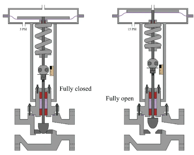
It is completely determined by two physical parameters:
- Spring stiffness
- Spring preload

Why do we need Bench Set?
Because a control valve does not operate in a vacuum.
After installation, it must be mounted in a pipeline and overcome forces from the process fluid, including forces that may:
- Push the plug open
- Hold the plug closed
- Create unbalanced forces on the valve trim
The spring is not only used for fail action.
It also provides:
Seat Load
(the force that keeps the valve tightly closed).
2. Scenario One: Fail Closed / Air-to-Open
Assume we have an air-to-open valve:
- Loss of air → spring closes the valve
- Air pressure → opens the valve
The process fluid flows from below the plug:
Flow to Open
Meaning the fluid pressure helps push the plug open.
The conflict:
When the valve is fully closed (0% opening), we do not only require it to be “closed”.
We require it to be:
Tightly sealed.
If the spring only pushes the plug onto the seat with exactly enough force (zero additional force), then even a small pipeline pressure of 1 bar could lift the plug slightly and cause internal leakage.
Solution: Shift the Bench Set
We need to increase spring preload.
The spring must be tightened so that, without any air pressure, it firmly pushes the plug against the valve seat.
Example:
- Standard range: 0.2 – 1.0 bar
- High-pressure application Bench Set: 0.8 – 2.4 bar
What does this mean?
0 bar air pressure:
The spring preload pushes the plug tightly against the seat.
It provides the required sealing force.
0.8 bar air pressure:
The pneumatic force just balances the spring preload.
The valve begins to open.
(Start to Open)
2.4 bar air pressure:
The valve reaches full open position.
Conclusion:
In this example, although the positioner input signal is:
4-20mA
the output air pressure from the positioner to the actuator must reach:
2.4 bar
to fully open the valve.
This is why your valve does not respond at 0.2 bar.
3. Scenario Two: Fail Open / Air-to-Close
Now let’s look at an:
Air-to-close valve
Meaning:
- Loss of air → spring opens the valve
- Air pressure → closes the valve
The process fluid is still:
Flow to Open
(the fluid pressure is pushing the plug upward).
The conflict:
When we need to fully close the valve (100% travel), the actuator air pressure must overcome two forces:
1. Fully compressed spring force
The spring is pushing the valve open.
2. Fluid unbalanced force
The process pressure is also trying to push the plug open.
The Birth of Installed Range
Example:
Bench Set:
0.2 – 1.0 bar
This means:
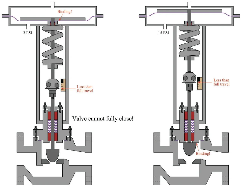
On a workshop bench, applying 1.0 bar air pressure can fully close the valve.
However, after installation:
Installed Range:
0.2 – 2.5 bar
Why?
Because the valve is now exposed to process pressure.
For example:
The pipeline pressure is 10 bar.
To overcome this additional hydraulic force, the actuator requires another:
1.5 bar
of air pressure.
Conclusion:
If you only provide 1.0 bar air pressure (standard signal range), the valve will never fully close in the field.
It will continue leaking.
4. Who Does the “Translation”? — The Positioner
At this point, you may ask:
“The DCS output is only 4-20mA (corresponding to 0.2-1.0 bar), and my instrument air supply is only 5 bar. How can the valve achieve a spring range of 0.8-2.4 bar?”
This is exactly why a:
Valve Positioner
exists.
The positioner is essentially a:
Power amplifier.
Input:
4-20mA
A weak electrical signal from the control system.
Output:
0-6 bar
A strong pneumatic signal.
(The actual output depends on the supply air pressure.)
During:
Auto Calibration
the positioner automatically detects the valve’s Bench Set.
Example:
The positioner detects:
“The valve starts moving at 0.5 bar.”
It records:
“When DCS sends 4.1mA, I should output 0.5 bar.”
The positioner detects:
“The valve requires 3.0 bar to fully close.”
It records:
“When DCS sends 20mA, I should output 3.0 bar.”
5. Summary: How to Understand a Valve Nameplate
Next time you see:
Bench Set: 0.8 – 2.4 bar
Understand it according to this logic:
1. This is not a fault
It is intentionally designed to:
- Overcome high process pressure
- Provide sufficient sealing force
2. The air supply must be sufficient
Your:
Filter Regulator
must be adjusted higher than the maximum Bench Set pressure.
Recommendation:
At least:
0.5 bar higher
For example:
Bench Set maximum:
2.4 bar
Recommended supply:
3.0 bar or higher
Otherwise, the valve may not open fully.
3. The positioner must be accurate
A new:
Stroke Calibration
must be performed.
The positioner needs to adapt to this “shifted” spring range.
One-Sentence Rule:
Bench Set is the “bare actuator performance” measured before installation.
Installed Range is the “real operating condition” after the valve is installed with process load.
The difference between them represents the force generated by the process fluid.