Control Valve Knowledge Series — No.007
Leakage Classes and Rangeability: The “Lower Limit” and “Upper Limit” of Control Valve Performance
Keywords: Leakage Class, ANSI/FCI 70-2, Rangeability, Turndown Ratio, Class VI
📝 Introduction
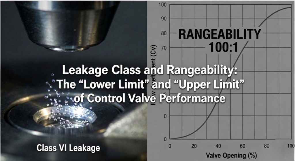
If the Cv value determines how much work a valve can do, then leakage class and rangeability determine how well it performs.
Leakage Class
The lower performance limit: How tightly can the valve shut off flow when closed?
Rangeability
The upper performance limit: How wide a flow range can the valve control effectively?
Many on-site problems occur not because a valve cannot pass enough flow, but because it cannot shut off tightly enough—causing high-pressure gas to leak into downstream systems or resulting in material waste—or because it cannot regulate flow effectively, leading to unstable operation at low flow rates and saturation at high flow rates.
In this article, we will explain these two key performance indicators that help determine a control valve’s capabilities.
01. Leakage Classes: The Art of Tight Shutoff
Absolute “zero leakage” does not exist in practice. Even between metal surfaces, microscopic gaps can remain.
The industrial standards commonly used for control valve seat leakage are ANSI/FCI 70-2 and its international counterpart, IEC 60534-4. These standards classify seat leakage into six classes.
Common Leakage Classes Explained
Class IV: The Standard for Metal-Seated Valves
Definition:
Seat leakage does not exceed 0.01% of the rated valve capacity (Cv) under the specified test conditions.
Applications:
Commonly used for many conventional single-seat and cage-guided control valves.
Practical Example:
For a valve with a Cv of 100, a small amount of leakage may be permitted. It may not be audible to the human ear, but measuring instruments can detect it.
Class V: A Significant Step Up in Tight Shutoff
Definition:
This class specifies very low seat leakage. The allowable leakage is calculated using a more complex formula involving factors such as the pressure differential and seat diameter. Under comparable conditions, the allowable leakage is typically much lower than for Class IV.
Applications:
Used in metal-seated valves requiring tighter shutoff. Achieving this performance often requires highly precise machining and lapping of the valve plug and seat.
Class VI: The Domain of Soft-Seated Valves
Definition:
Often associated with bubble-tight shutoff, Class VI specifies a very low allowable leakage rate.
Test Method:
Air or another specified test gas is passed through the closed valve, and the leakage is measured according to the prescribed test procedure. For example, for a 1-inch valve, the allowable leakage under the applicable test conditions may be as low as one bubble per minute.
Materials:
This class is commonly achieved using soft sealing materials such as PTFE (polytetrafluoroethylene) or elastomers.
Limitations:
Soft-seat materials have temperature and chemical-compatibility limitations. The maximum service temperature depends on the specific material and valve design; PTFE-based seats may have limitations at elevated temperatures.
💡 Common Valve Selection Mistake
Do not automatically choose Class VI for every application. For high-temperature, high-pressure steam service, insisting on Class VI may require a costly special design, and the suitability and service life of the sealing materials must be carefully evaluated. For many control applications, Class IV may provide adequate shutoff performance.
Important: The actual leakage class must be selected according to the process requirements, operating conditions, applicable standards, and the manufacturer’s certified performance data.
02. Rangeability: Theory vs. Reality
Rangeability is also known as the turndown ratio.
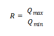
Definition: The ratio of the maximum controllable flow rate to the minimum controllable flow rate under specified conditions.
Linear-Characteristic Valves:
The inherent rangeability may be around 30:1, depending on the valve design.
Equal-Percentage Valves:
The inherent rangeability may be 50:1 or even 100:1, depending on the design and manufacturer.
Why Can the “100:1” in a Product Catalog Be Misleading?
The value stated in a manufacturer’s catalog is usually the inherent rangeability—the rangeability measured under specified test conditions, typically with a constant pressure drop across the valve.
In an actual installation, however, we need to consider the installed rangeability.
Remember the valve authority, S, discussed in No.002?
Pressure losses in the piping system affect the pressure differential available across the valve, which can significantly reduce its effective control range.
When S = 1 (an idealized condition), the pressure drop across the valve remains essentially constant, so installed rangeability can approach inherent rangeability.
When S = 0.1, the valve has relatively low authority. A valve with a nominal inherent rangeability of 50:1 may have a much smaller installed rangeability. The actual value depends on the system curve, valve characteristic, and operating conditions; it should not be assumed to be exactly 5:1.
What does this mean in practice?
As the required flow decreases, the valve may approach its nearly closed position, where friction, deadband, actuator resolution, and other factors can make precise control difficult. The result may be unstable or inaccurate flow regulation.
✅ Engineering Guideline
Do not rely solely on catalog rangeability figures. For systems with low valve authority, evaluate the installed rangeability under realistic operating conditions.
If the process requires a very wide flow range—for example, extremely low flow during startup and much higher flow during normal operation—a single valve may not provide satisfactory control across the entire range.
One possible solution is to use two valves of different sizes in parallel, often referred to as a split-range arrangement. A smaller valve handles low-flow operation, while a larger valve handles higher flow rates. The control strategy and valve sizing must be designed carefully to ensure smooth transitions and stable operation.