Why do we recommend the seemingly complex “equal percentage” valve over the intuitively simple “linear” valve in 90% of process control applications?
Many engineers assume that controlling a linear process requires a linear valve. This is a massive misconception. In real-world piping systems, ideal “inherent characteristics” are inevitably distorted by harsh realities into “installed characteristics.”
In this edition, we’ll uncover the engineering truth behind flow characteristic curves.
01. The Ideal World: Inherent Flow Characteristics
“Inherent characteristics” refer to the curve measured under ideal laboratory conditions.
Test Condition: A constant pressure drop (ΔP) across the valve.
Under these ideal circumstances, the valve’s flow coefficient (Cv) depends solely on the geometry of the trim.
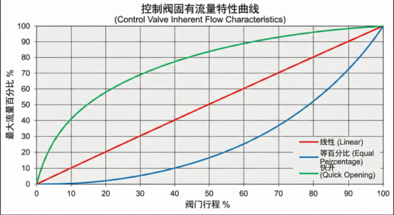
The Three Main Camps:
- Linear:
Definition: For every 10% increase in valve opening, the Cv value increases by a fixed 10%. There is a strict, direct proportional relationship between flow and opening.
Trim Appearance: Typically a sleeve with rectangular windows or a standard parabolic plug. - Equal Percentage:
Definition: For every equal percentage increase in valve opening, the Cv value increases by the same percentage relative to its previous value.
Features: The curve rises exponentially. At small openings, flow changes very gradually (allowing for fine-tuning); at large openings, flow changes extremely rapidly.
Trim Appearance: Usually a sleeve with specialized V-port windows or a grooved plug. - Quick Opening:
Definition: Achieves a massive flow rate at a very small opening (typically <30%).
Application: Primarily used for On-Off shut-off; rarely used for modulating control.
👇 Key Graphic: Ideal Curves in the Lab
02. The Real World: Installed Flow Characteristics
However, once you install the valve in an actual plant pipeline, everything changes.
In real piping networks, as the valve opens wider and flow increases, the resistance loss from pipes, elbows, manual valves, and other components also increases.
The Consequence: The pressure drop (ΔP) allocated to the control valve is no longer constant; it decreases as the valve opening increases.
The Culprit Behind the Scenes: Valve Authority (S)
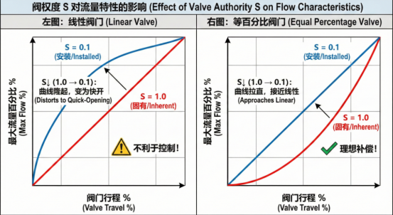
To quantify how much the piping system “distorts” the valve’s characteristics, we introduce a critical parameter: Valve Authority (S).
It represents the ratio of the pressure drop across the fully open valve to the total pressure drop of the entire system.
S = 1 (Ideal): No other system resistance; valve ΔP is constant. Installed characteristics = Inherent characteristics.
S < 1 (Reality): The lower the S value, the greater the pipe resistance and the smaller the pressure drop available to the valve.
👇 Key Graphic: How Reality Distorts the Curve
03. Why Use “Equal Percentage”? For Compensation!
Now, the answer becomes clear.
Our ultimate goal is to achieve a linear response throughout the entire control loop.
In other words, a 10% change in the controller’s output signal should result in a 10% change in the final process variable (e.g., flow, temperature).
In most industrial applications (where the S value typically ranges from 0.3 to 0.5), the resistance effect of the piping system is nonlinear.
If you choose a linear valve: Combined with the nonlinear piping system, the final result is severe nonlinearity (too sensitive at low openings, too sluggish at high openings).
If you choose an equal percentage valve: Its concave inherent characteristic perfectly offsets (compensates for) the pressure drop caused by the piping system.
The Bottom Line: Two negatives make a positive.
The inherent characteristic of an “equal percentage” valve + realistic pipe resistance ≈ a “linear” installed characteristic.
04. The Engineer’s Selection Rule
Once you understand the principle, selection becomes straightforward:
Default to Equal Percentage: For the vast majority of flow, pressure, and temperature control loops—especially in systems with long pipelines and high system resistance (S < 0.5)—choose equal percentage without hesitation. It is the best “compensator” for maintaining control loop stability.
When to Use Linear: When the system pressure drop is essentially constant (S approaches 1), such as in certain level control applications or pressure-reducing-only scenarios. Also applicable to three-way valves used for diverting or mixing.
Beware of Quick Opening: Unless you are selecting an Emergency Shutdown Valve (ESD), never use quick-opening characteristics in a modulating control loop. It will cause extreme system instability and oscillation.