Executive Overview of Linear Motion Control Systems
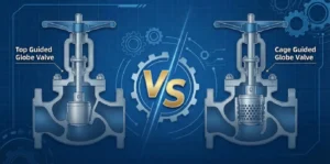
What is Globe Valves? The industrial globe valve is a sophisticated linear-motion valve primarily designed for stopping, starting, and regulating fluid flow. Unlike the simplistic gate valve, which operates on a binary isolation principle, the globe valve utilizes a disc (plug) that moves perpendicularly to the seat. This mechanical arrangement allows for precise throttling, making it the indispensable choice for systems requiring regulated pressure and flow velocity, such as high-pressure steam headers, chemical dosing lines, and boiler feedwater systems.
The structural evolution of the globe valve reflects the increasing rigors of industrial processes. From the early cast iron stop valves to modern API 623-compliant stainless steel units produced by SFANVALVE, the engineering focus has shifted from basic isolation to long-term reliability in severe service. The internal geometry—a tortuous “Z” or “Y” shaped path—forces the medium to change direction twice, a design trade-off that provides superior control at the expense of a higher pressure drop compared to ball or gate valves. In the following sections, this report analyzes the standard frameworks, metallurgical advancements, and digital procurement trends defining the 2026 valve market.
1. Technical Standards and Regulatory Frameworks: API 623 vs. BS 1873
The transition from the legacy BS 1873 standard to the modern API 623 represents a paradigm shift in the downstream refinery and petrochemical sectors. While BS 1873 served as the baseline for cast steel globe valves for decades, it lacked the robustness required for modern severe-service environments.
1.1 Dimensional and Mechanical Upgrades in API 623
API 623 was developed to mirror the heavy-duty specifications of the API 600 gate valve standard. The most critical differentiator is the mandate for thicker wall construction. According to the standard, most valve sizes must possess a wall thickness at least 3mm greater than the minimums required by ASME B16.34. This additional “sacrificial” material significantly enhances the valve’s resistance to erosion and corrosion, extending its operational lifespan in high-velocity steam or chemical services.
Furthermore, API 623 specifies larger stem diameters than its predecessor. For a 6-inch Class 600 globe valve, the API 623 stem diameter is 48mm, whereas the BS 1873 equivalent may only be 41.3mm. A larger stem diameter increases the cross-sectional area, enhancing the valve’s resistance to yielding and buckling under the high compressive loads required for bubble-tight sealing in high-pressure environments.
1.2 Comparison of Technical Parameters
| Technical Parameter | BS 1873 (Standard Class) | API 623 (High Specification) |
| Industry Focus | Light industrial, general utilities | Downstream refinery, petrochemical |
| Wall Thickness | Per ASME B16.34 | Heavier than ASME B16.34 (approx. +3mm) |
| Stem Diameter | Standard industrial minimums | Enhanced diameter for high-torque sealing |
| Disc Guiding | Basic guiding required | Full-stroke guiding mandated |
| Fugitive Emissions | No specific test requirement | Must meet API 624 (Low Emission) |
| Pressure Ratings | Class 150 to 2500 | Class 150 to 2500 |
SFANVALVE ensures that its high-performance globe valves are dual-compliant, exceeding the requirements of BS 1873 to meet the more rigorous API 623 standard, thereby providing a superior safety margin for global energy projects.
2. Structural Design Variations and Fluid Dynamics
The internal body pattern of a globe valve dictates its flow coefficient (Cv) and its suitability for specific industrial applications. Engineering a globe valve requires a balance between control precision and energy loss.
2.1 The Z-Body Pattern: Precision Throttling
The Z-body, or T-pattern, is the most common configuration. The seat is arranged horizontally, forcing the stem and disc to travel perpendicular to the flow axis. This design creates a highly tortuous path, resulting in the highest pressure drop of any valve design (with a typical L/D ratio of ~340). However, this resistance is what allows for the exceptional throttling accuracy of SFANVALVE’s Z-body units. They are ideally suited for bypass lines around control valves where pressure drop is a secondary concern to flow regulation.
2.2 The Y-Body Globe Valve (Wye) Pattern: Efficiency in High Pressure
To mitigate the energy losses of the Z-pattern, the Y-body globe valve positions the stem and seat at an angle, typically 45 degrees, to the main pipeline. This design streamlines the flow path, reducing turbulence and the resistance coefficient (ζ) by approximately 25% to 30%. In critical services like boiler feedwater or high-pressure steam, the Y-pattern is the preferred choice as it minimizes erosion and vibration while maintaining excellent throttling capabilities.
2.3 The Angle Body Pattern: Integrated Pipe Optimization
The angle globe valve turns the flow direction by 90 degrees, allowing it to function as both a valve and a pipe elbow. This configuration significantly reduces the number of fittings and welds required in a piping system, lowering both installation costs and potential leak paths. Angle valves are particularly effective in handling pulsating flow due to their ability to manage the “slugging effect” inherent in such systems.
2.4 Flow Performance Matrix
| Body Design | Flow Efficiency (Cv) | Typical Application | Pressure Drop |
| Z-Type (Straight) | Low (approx. 80 for DN100) | Precision dosing, sampling | High |
| Y-Type (Oblique) | Moderate (approx. 100 for DN100) | High-pressure steam, boiler feed | Moderate |
| Angle (90°) | High (relative to Globe) | Pulsating flow, piping corners | Low |
3. Metallurgical Engineering and Material Selection
Material selection is the primary determinant of a globe valve’s operational integrity. For SFANVALVE, material science involves matching the chemical composition of the valve body and trim to the specific corrosive and thermal properties of the media.
3.1 Carbon Steel and Alloy Steel (ASME B16.34)
Standard industrial globe valves utilize ASTM A216 WCB for temperatures between -29°C and 427°C. However, for high-temperature steam in power generation, alloy steels such as WC6 (1.25% Cr – 0.5% Mo) and WC9 (2.25% Cr – 1% Mo) are required. These alloys provide enhanced creep resistance and tensile strength at temperatures up to 593°C.
3.2 Stainless Steel and High-Alloy Performance
For corrosive chemical processing, ASTM A351 CF8M (cast 316 SS) is the global standard. The inclusion of 2-3% Molybdenum in CF8M provides critical resistance to pitting and crevice corrosion in chloride environments. In more aggressive scenarios, such as offshore deep wells or sulfuric acid processing, SFANVALVE offers Duplex (Grade 4A/5A) and Super Duplex materials that combine high yield strength with exceptional resistance to stress corrosion cracking (SCC).
3.3 API 600 Trim Classifications
The “Trim” consists of the wetted internal parts: the seat surface, disc surface, stem, and backseat bushing. API 600 defines standard trim numbers, with Trim #8 (Stellite hard-facing) being the most common for high-pressure industrial service due to its extreme hardness and resistance to “wire drawing” (erosion caused by high-velocity fluid).
| Trim No. | Material Type | Seat Surface | Typical Service |
| Trim 5 | Hardfaced (Stellite) | Co-Cr A | Severe service, high-pressure steam |
| Trim 8 | 13Cr/Hardfaced | Co-Cr A | Standard industrial, oil, and gas |
| Trim 10 | 316 SS | 316 SS | Chemical, corrosive (non-erosive) |
| Trim 12 | 316/Hardfaced | Co-Cr A | Corrosive media with high pressure |
4. Sealing Integrity and Leakage Standards
Ensuring a bubble-tight seal is a hallmark of SFANVALVE engineering. Globe valves are superior to gate valves in shut-off tightness because the disc-to-seat contact is perpendicular, enabling high contact pressure with relatively low operating torque.
4.1 Internal Seat Leakage (FCI 70-2 and ISO 5208)
Leakage classes define the maximum permissible internal leakage during testing. For metal-seated industrial globe valves, Class IV (per FCI 70-2) is the standard, allowing a leakage of 0.01% of the rated flow. For critical isolation, SFANVALVE units can be engineered to Class V or VI, where Class VI (bubble-tight) is typically achieved using resilient (soft) seats such as PTFE or Devlon.
4.2 External Fugitive Emission Control
5. Industrial Applications: Engineering Case Studies
5.1 High-Pressure Steam in Power Plants
In a thermal power facility, the main steam isolation valve must handle superheated steam at 540°C. Using a standard gate valve led to seat erosion within six months due to intermittent throttling during startup. Replacing it with an SFANVALVE API 623-compliant Y-pattern globe valve (WCB body, Trim #5) resulted in zero leakage over two years of operation, saving the plant an estimated $40,000 in annual steam loss.
5.2 Chemical Reactor Feed Systems
A petrochemical plant processing corrosive catalysts required a valve for ±1% flow adjustment. The high-velocity media caused rapid failure in standard ball valves. An SFANVALVE CF8M globe valve with a parabolic plug design provided the necessary logarithmic flow characteristics, maintaining control stability for over 50,000 cycles.
6. Operational Maintenance and Lifetime Optimization
The total cost of ownership (TCO) of a globe valve is determined by its maintenance profile. Globe valves are favored for their “top-entry” design, allowing the seat and disc to be serviced or replaced without removing the valve from the line.
- Packing Maintenance: Regular inspection of the gland packing is critical. SFANVALVE recommends periodic adjustments to the gland nuts to ensure a constant load on the graphite rings.
- Startup Procedure: Slow warm-up is essential in steam systems to prevent water hammer and thermal shock to the valve body.
7. Conclusion: The Future of Smart Valve Engineering
As the industry moves toward 2030, the integration of IoT-enabled sensors will transform the globe valve into a “smart asset.” SFANVALVE is currently developing real-time torque and leak detection modules that integrate with plant asset management systems via WirelessHART. This transition from reactive to predictive maintenance will define the next generation of industrial fluid control, ensuring that global infrastructure remains safe, efficient, and environmentally compliant.